As a metal insert mould supplier, I've witnessed firsthand the transformative power of simulation software in our industry. Simulation software has become an indispensable tool, enabling us to predict and optimize the complex processes involved in metal insert mould design. It offers a virtual environment to test different scenarios, reduce physical prototyping, and speed up the design cycle. However, like any technology, it comes with its own set of limitations that can significantly impact the accuracy and effectiveness of our designs.
Material Behavior Complexity
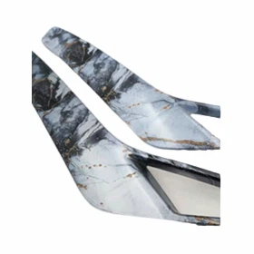
One of the primary challenges with simulation software in metal insert mould design is accurately representing the behavior of materials. When dealing with metal inserts, we encounter a wide range of materials each with unique properties such as thermal conductivity, elasticity, and ductility. For example, in the production of Silicon Steel Sheet Insulator, the silicon steel has specific magnetic and electrical properties that can affect the moulding process.
Simulation software typically relies on pre - defined material models. These models are approximations based on average data and may not capture the full complexity of real - world materials. Small variations in the material composition, such as impurities or changes in the manufacturing process of the silicon steel, can lead to different behaviors during moulding. For instance, a slight change in the carbon content of a metal insert can alter its hardness and ductility, influencing how it interacts with the plastic during the injection moulding process. The software may not account for these subtle differences, resulting in inaccurate predictions of factors like stress distribution and deformation in the final moulded part.
Boundary Conditions and Real - World Variability
Another significant limitation is the difficulty in accurately defining boundary conditions. In a real - world metal insert moulding process, there are numerous factors that can affect the outcome, including temperature variations, pressure fluctuations, and the presence of lubricants. Simulation software requires us to input these boundary conditions, but it's nearly impossible to replicate the exact conditions of a production environment.
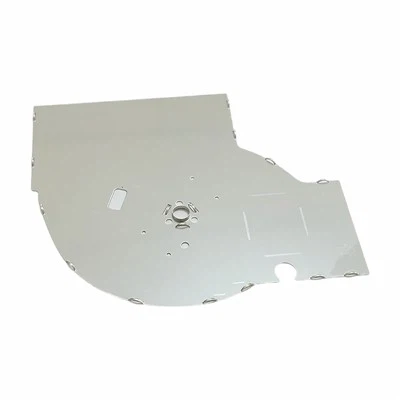
For example, during the production of Pillow Assy, the temperature of the mould and the molten plastic can vary depending on the ambient temperature, the duration of the production run, and the efficiency of the cooling system. The software may assume a constant temperature, but in reality, the temperature can change rapidly during the injection and cooling phases. These temperature variations can cause the plastic to shrink or expand at different rates, leading to warping or dimensional inaccuracies in the final product that the simulation may not predict.
Similarly, pressure fluctuations in the injection moulding machine can also have a significant impact on the moulding process. The software may use a fixed pressure value, but in practice, the pressure can vary due to factors such as the viscosity of the plastic, the flow rate, and the resistance in the mould cavity. These real - world variations can result in incomplete filling of the mould, air traps, or uneven distribution of the plastic around the metal insert.
Meshing and Geometric Simplification
Simulation software relies on meshing, the process of dividing a complex geometry into smaller elements, to analyze the physical behavior of the mould and the insert. The quality of the mesh can have a profound impact on the accuracy of the simulation results. In metal insert mould design, the geometries are often highly complex, with intricate shapes and fine details.
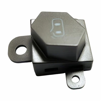
When creating a mesh, there is a trade - off between accuracy and computational time. To reduce the computational load, the software may require us to simplify the geometry of the metal insert and the mould. For example, small features such as holes, ribs, or fillets may be removed or approximated. While these simplifications can speed up the simulation, they can also introduce errors. In the design of EV Busbar Connector, which has complex geometries to ensure proper electrical conductivity and mechanical stability, any geometric simplification can lead to inaccurate predictions of the stress distribution and the flow of the plastic around the metal insert.
Moreover, the meshing process itself can be challenging. Irregular or poorly defined meshes can result in numerical errors, such as inaccurate calculation of forces and displacements. These errors can accumulate and lead to significant discrepancies between the simulation results and the actual performance of the moulded part.


Lack of Dynamic Interaction Modeling
Most simulation software for metal insert mould design focuses on static analysis, which means it analyzes the system at specific points in time rather than considering the dynamic nature of the moulding process. In reality, the metal insert and the plastic interact continuously during the injection, packing, and cooling phases.
For example, during the injection phase, the molten plastic flows around the metal insert, exerting forces on it. The insert may deform slightly under these forces, which in turn can affect the flow of the plastic. This dynamic interaction between the plastic and the metal insert is difficult to model accurately in current simulation software. As a result, the software may not be able to predict phenomena such as the movement of the insert during the moulding process or the formation of weld lines, which can weaken the final part.
Validation and Calibration Challenges
To ensure the reliability of simulation results, it's essential to validate and calibrate the software against real - world data. However, this process can be time - consuming and expensive. In our experience, obtaining accurate experimental data for metal insert moulding can be challenging due to the complexity of the process and the difficulty in measuring certain parameters, such as the internal stress distribution in the moulded part.
Moreover, the calibration process requires adjusting the input parameters of the simulation software to match the experimental results. This can be a trial - and - error process, as there are often multiple parameters that can affect the simulation outcome. For example, changing the material properties, the boundary conditions, or the meshing parameters can all have an impact on the results. Without a systematic approach to calibration, it's easy to introduce new errors or biases into the simulation.
Implications for Metal Insert Mould Design
These limitations of simulation software have several implications for our work as a metal insert mould supplier. First, it means that we cannot rely solely on simulation results to design and optimize our moulds. We still need to conduct physical prototyping and testing to verify the performance of our designs. This not only adds time and cost to the development process but also requires a significant amount of resources.
Second, the limitations of the software can lead to design errors and inefficiencies. If the simulation results are inaccurate, we may design moulds that do not perform as expected, resulting in poor - quality products, increased scrap rates, and longer production cycles. This can have a negative impact on our competitiveness in the market.
Looking Forward
Despite these limitations, simulation software remains an important tool in metal insert mould design. It provides valuable insights into the moulding process and allows us to explore different design options quickly. To overcome the limitations, we need to continue to invest in research and development to improve the accuracy of the software. This includes developing more accurate material models, better methods for defining boundary conditions, and advanced meshing techniques.
In addition, we need to integrate simulation software with other technologies, such as real - time monitoring and feedback control systems. By collecting data from the production process and using it to adjust the simulation parameters, we can improve the accuracy of the predictions and optimize the moulding process in real - time.
Contact for Purchase and Collaboration
If you are in the market for high - quality metal insert moulds and are interested in discussing how we can overcome these challenges together, we'd love to hear from you. Our team of experts is ready to work with you to design and manufacture the best - in - class metal insert moulds that meet your specific requirements. Whether you need a mould for Silicon Steel Sheet Insulator, Pillow Assy, EV Busbar Connector, or any other application, we have the experience and expertise to deliver. Contact us today to start the conversation about your metal insert mould needs.
References
- Smith, J. (2018). Advanced Injection Molding Simulation Techniques. Wiley.
- Johnson, R. (2020). Material Behavior in Metal Insert Molding. Journal of Manufacturing Science.
- Brown, S. (2019). Challenges in Mould Design Simulation. International Journal of Precision Engineering.